
Canal falls represent a fundamental engineering solution within irrigation systems, crucial for the effective management of water flow and the prevention of erosion in diverse topographical conditions. These structures are strategically integrated into canal beds to facilitate a controlled descent of water from higher to lower elevations. This article delves into the definition, necessity, location, various types, and design principles of canal falls, highlighting their indispensable role in supporting agricultural productivity and water resource management.
The Imperative for Canal Falls: Why They Are Built
The primary reason for constructing canal falls arises when the natural ground slope is steeper than the designed bed slope of the channel. Irrigation canals are engineered with a specific bed slope to ensure water velocity is neither silting (depositing sediment) nor scouring (eroding the bed). When the ground drops suddenly or maintains a slope significantly greater than the canal's designed slope, constructing vertical 'falls' or 'drops' adjusts this difference. Without these structures, maintaining the designed canal slope would necessitate excessive earthwork in filling, leading to uneconomical project costs.
A natural drop in a canal bed would be inherently unstable. Therefore, a masonry structure is constructed to retain this drop, which is then termed a canal fall or canal drop. Beyond merely adjusting levels, canal falls are designed to destroy or dissipate the surplus energy generated by the falling water. This energy dissipation is vital to prevent erosion downstream and maintain a stable water level, thereby reducing the risk of flooding and damage to infrastructure. Canal falls also play a role in cross-drainage works, particularly when the canal's full supply level (F.S.L.) is above the bed level of a drainage system, necessitating the canal water to be carried below the stream or drainage.
Strategic Placement: Locating Canal Falls
The proper location of a fall in a canal is not arbitrary; it heavily depends on the topography of the country through which the canal passes. For main canals that do not directly irrigate an area, the site selection is driven by economic considerations, specifically balancing the 'cost of excavation and filling' versus the 'cost of fall'. It is crucial to attempt to balance the excavation and filling on both sides of a fall, as unbalanced earthwork can significantly increase project costs. An economic analysis between these factors is essential before finalizing the locations and extent of falls.
Types of Canal Falls
Various types of canal falls have been designed and implemented since their inception, ranging from older designs to those used in modern days. These can be broadly categorized based on their design and functionality into vertical drop, inclined drop, and stepped falls.
-
Ogee Falls: This type of fall, constructed in olden days on projects like the Ganga Canal by Sir Proby Cautley, features gradual convex and concave curves (in the ogee form). The purpose of these smooth transitions is to reduce disturbance and impact, and a hydraulic jump is formed to dissipate kinetic energy. Stone pitching is typically provided upstream and downstream of the fall. Ogee falls provide smooth transition of flow and reduce disturbance and impact.
-
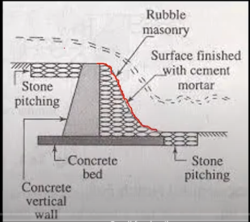
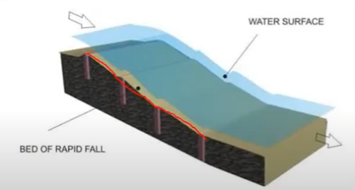
Rapids / Rapid Falls: Utilized in canals like the Western Yamuna canal, rapids consist of a long sloping glacis (generally 1:15 to 1:20). These were historically provided with boulder facings and worked satisfactorily but proved very expensive, leading to their obsolescence. Curtain walls are provided on both upstream (u/s) and downstream (d/s) sides, with rubble masonry finished with rich cement mortar protecting the bed. They are suitable when the natural ground level is even and rapid.
-
Trapezoidal Notch Falls: Designed by Ried in 1894, this fall type consists of multiple trapezoidal notches built into a high-crested wall across the channel. Each notch has a smooth entrance and a flat, circular lip projecting downstream to spread out the falling water jet. The sill of the notches is typically kept at the upstream bed level of the canal. They are considered economical and suitable for low discharges. The body wall is made of concrete, and an impervious floor is provided to resist scouring.
- Design Principles for Trapezoidal Notch Fall: This fall type provides a proportionate fall, meaning there is no significant heading up or drawdown of water level near the fall. The total width of the channel is divided into several notches. While the crest (sill level) can be higher than the canal bed, the total length of the weir openings should not exceed the upstream canal bed width and can be reduced to about 7/8th of the bed width. The discharge (Q) through one trapezoidal notch is given by a formula combining rectangular and V-notch discharges: Q = (2/3) * C_d * sqrt(2g) * [lH^(3/2) + (4/5) * tan(α/2) * H^(5/2)]. This simplifies to Q = 2.22 H^(3/2) * [l + 0.4nH] where C_d ≈ 0.75 and n = 2 * tan(α/2). Design usually involves assuming two discharge values (e.g., full supply Q100 and half supply Q50) and corresponding water depths (H100=Y100, H50=Y50) to solve for 'l' and 'n'. The depth at 50% discharge (y50) can be approximated as 0.66 times the full supply depth (y100). The number of notches is adjusted through trial and error so that the top width of the notch is between 1/2 and 3/4 of the full water depth above the sill. Notch pier thickness should be at least half the water depth, with top length not less than thickness.

-
Well Type Falls / Cylinder Falls / Syphon Well Drops: In this design, water from a higher canal level is directed into an inlet well, from which it flows through a pipe at the bottom to a downstream well or cistern. Energy dissipation occurs due to turbulence inside the well. A downstream well is necessary for falls greater than 1.8 m or discharges exceeding 0.29 cumecs. These falls are suitable and economical for low discharges.

-
Simple Vertical Drop Type and Sarda Type Falls: This fall features a raised crest with a vertical impact, where water falls into a pool of water on a depressed floor (cistern) to act as a cushion and dissipate excess energy. First introduced on the Sarda Canal System in U.P., it gained popularity due to its economy and simplicity, particularly for constructing many smaller falls.
- Design Principles for Sarda Type Fall: These falls are typically not flumed. For canal discharges of 15 cumecs or more, the crest length equals the canal's bed width; for distributaries and minors, it is bed width plus depth of flow. The body wall is rectangular for discharges less than 14 m³/s, and trapezoidal (u/s batter 1:3, d/s batter 1:8) for larger discharges. Key dimensions include top width 'b' and base width 'B' (calculated based on depth of water above crest 'H' and crest height above d/s bed 'd'). The discharge formula under free fall is Q = CLH {H/b}^(1/6), where C is 2 for trapezoidal and 1.85 for rectangular crests. The crest level is fixed so that the upstream flow depth is unaffected. Cistern dimensions are crucial for energy dissipation, with formulas like Lc = 5√(E·HL) used for length. Total impervious floor length is designed based on theories like Bligh's or Khosla's to resist uplift and ensure safety against exit gradient. Cut-offs are provided at both u/s and d/s ends of the floor. Upstream wing walls may be splayed or segmental, while downstream wing walls are vertical initially, then flared. Staggered blocks are provided on the cistern floor or end of the impervious floor for additional energy dissipation. Bed and side pitching are also provided for protection.

-
Straight Glacis Falls: A modern fall type, it features a 'straight glacis' (typically sloping 2:1) provided after a 'raised crest'. The design promotes a hydraulic jump on the glacis for sufficient energy dissipation. They offer good performance if unflumed but can be flumed for economy. These are suitable for discharges up to 60 cumecs and drops up to 1.5 m.
- Design Principles for Straight Glacis Fall: Unlike vertical falls, glacis falls can be flumed, especially when combined with a bridge, to reduce costs. However, fluming should not lead to excessive discharge intensity causing scour. The crest level is related to the upstream total energy level (TEL). The upstream glacis for non-meter falls has a 1/2:1 slope, curving into the crest with a radius of E/2. The downstream glacis has a 2:1 slope, joining the cistern with a curve of radius E. Cistern dimensions (e.g., RL of cistern = d/s TEL - 1.25Ef2, length of cistern = 5Ef2 for good soil) facilitate hydraulic jump formation on the glacis. Cut-offs are provided at both ends of the impervious floor, with depths D1/3 u/s and D2/2 d/s. The total length of impervious floor is determined by permissible exit gradient using Khosla’s curves. Thickness of the floor must withstand uplift pressure. Upstream approach walls may be splayed at 45° for non-meter falls. Downstream expansion should be gradual, often following Mitra’s hyperbolic equation, to prevent scour. Friction blocks are highly effective energy dissipators, typically provided in rows on the glacis or cistern floor.

-
Montague Type Falls: An improvement on the straight glacis fall, this type replaces the straight glacis with a 'parabolic glacis,' known as the 'Montague Profile'. This parabolic shape enhances energy dissipation by influencing the vertical component of velocity. The Montague profile is defined by the equation X = U * sqrt(4Y/g) + Y, where X and Y are horizontal and vertical ordinates, U is initial velocity, and g is gravity.

-
Inglis Falls or Baffle Falls: This design modifies a straight glacis fall by adding a baffle platform and a baffle wall. Developed by Inglis, these falls are suitable for all discharges and drops greater than 1.5 m, and can be easily flumed for economy. The baffle wall is precisely positioned (calculated height and distance from glacis toe) to ensure the formation of the hydraulic jump on the baffle platform, maximizing energy dissipation. Main body of glacis is concrete, with essential stone pitching at u/s and d/s ends.

-
Stepped Falls: Consisting of a series of vertical drops in the form of steps, this type is a modification of a rapid fall. Stepped falls are suitable for long, sloping grounds requiring a long glacis to connect high upstream bed levels with lower downstream levels. Brick walls are provided at each drop, and the canal bed within the fall is protected by rubble masonry with cement mortar finishing to prevent erosion. While effective for energy dissipation and flow control, they can have higher construction costs and more complex maintenance.

Functional Classifications of Canal Falls
Canal falls can also be classified based on their functional characteristics:
- Meter and Non-Meter Falls: Meter falls are those designed to also measure the canal's discharge. Non-meter falls do not perform this function. Generally, glacis type falls are suitable as meters, whereas vertical drop falls are not, due to the potential for partial vacuum formation under the water nappe.
- Flumed and Unflumed Falls: A fall can be constructed either across the full channel width (unflumed) or with a contracted width (flumed). Flumed falls are often adopted for economy, especially when combined with other structures like bridges. However, unflumed falls (like vertical drops) are sometimes preferred to avoid increased discharge intensity and subsequent scour downstream.
Key Principles in Canal Fall Construction
The successful design of canal falls integrates several critical factors and hydraulic principles.
- Factors Influencing Design:
- Topography: The slope and elevation of the surrounding terrain dictate the type and number of falls needed.
- Water flow rates: The volume and velocity of water significantly impact energy dissipation requirements and structural stability.
- Sediment transport: The amount and type of sediment carried by the water influence scour protection and maintenance needs.
- Hydraulic Design Principles:
- Energy dissipation: This is paramount to prevent erosion downstream. It involves reducing the excess kinetic energy of the falling water, often through hydraulic jumps, water cushions, or baffle structures. The energy dissipation can be calculated using the equation: ΔE = (V1² - V2²) / (2g), where ΔE is energy dissipation, V1 and V2 are upstream and downstream velocities, and g is acceleration due to gravity.
- Flow control: Regulating water flow maintains a stable water level upstream and ensures efficient water distribution.
- Structural Design Considerations:
- Materials: Common construction materials include brick masonry and mass concrete, especially in modern projects. Older structures often used boulder masonry.
- Stability: The structure must be designed to withstand various external forces, including water pressure, uplift pressures, and sediment loads.
Construction and Maintenance Practices
The long-term effectiveness of canal falls relies heavily on meticulous construction and consistent maintenance.
- Best Practices for Construction:
- Site preparation: Thorough clearing and excavation are essential to establish a stable foundation for the structure.
- Material selection: Choosing appropriate materials like concrete or masonry ensures durability and structural integrity.
- Maintenance Requirements:
- Inspection: Regular inspections are crucial to identify any signs of damage, deterioration, or potential issues early on.
- Repair: Prompt repair of damaged components prevents further, more extensive problems.
- Replacement: Components beyond repair must be replaced to maintain the fall's functionality and safety.
Common Issues and Troubleshooting:
- Erosion: Often caused by high water flow rates, it can be mitigated by reducing flow rates or implementing erosion control measures like pitching.
- Sedimentation: High sediment loads can lead to deposition. Troubleshooting involves implementing sediment control measures, such as silt ejectors or scouring escapes (though the latter is becoming obsolete).
- Structural damage: This can stem from poor design or construction. Solutions involve inspecting and repairing damaged components, or replacing them if necessary.
Conclusion
Canal falls are indispensable components of irrigation systems, serving critical functions in managing water levels, regulating flow, and dissipating surplus energy to prevent erosion. From historical Ogee and Rapid falls to modern Glacis and Baffle falls, each type offers specific advantages depending on topographical conditions, discharge rates, and economic considerations. The intricate design principles, encompassing hydraulic and structural considerations, along with diligent construction and maintenance practices, are vital for ensuring the longevity and effectiveness of these structures in supporting agricultural productivity and overall water resource management. Their continued evolution reflects ongoing efforts in civil engineering to optimize water infrastructure for sustainable development.
Post a Comment